Welcome to my Astromech build. I started documenting this in December of 2015, and will try to continue documentation on this site.
Goal:
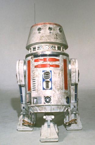
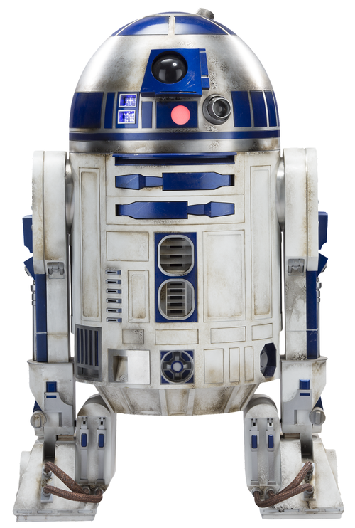
My plan is to make both the R5-D4 head and the R2-D2 head on a single body, which can convert to either Astromech. Their are only subtle color changes on the body which can be easily replaced based on which Astromech is being presented. The parts will be a combination of aluminum, wood, resin and 3D printed plastic based on availability. Any 3D printed parts will not be attached “permanently” to allow the ability to upgrade later.
2015 – December
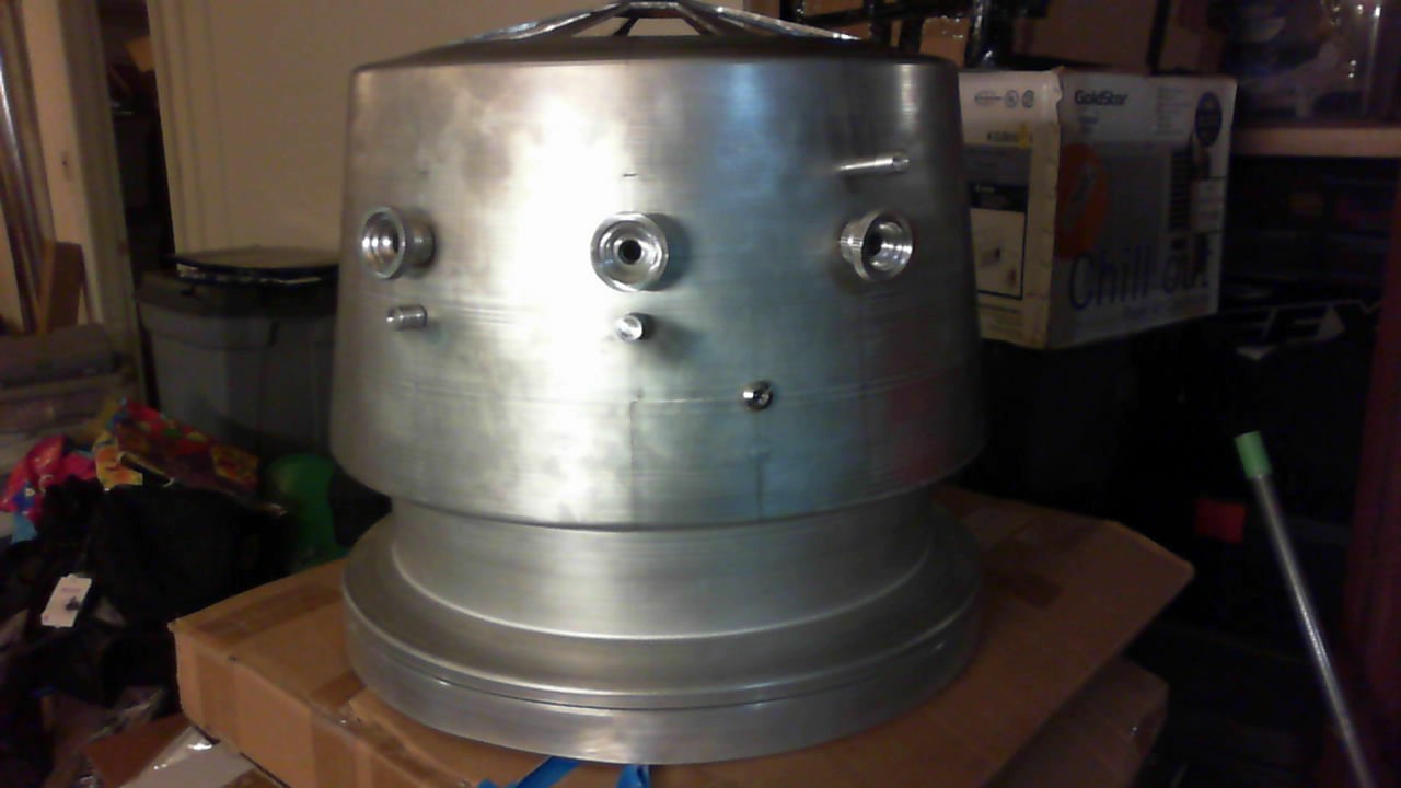
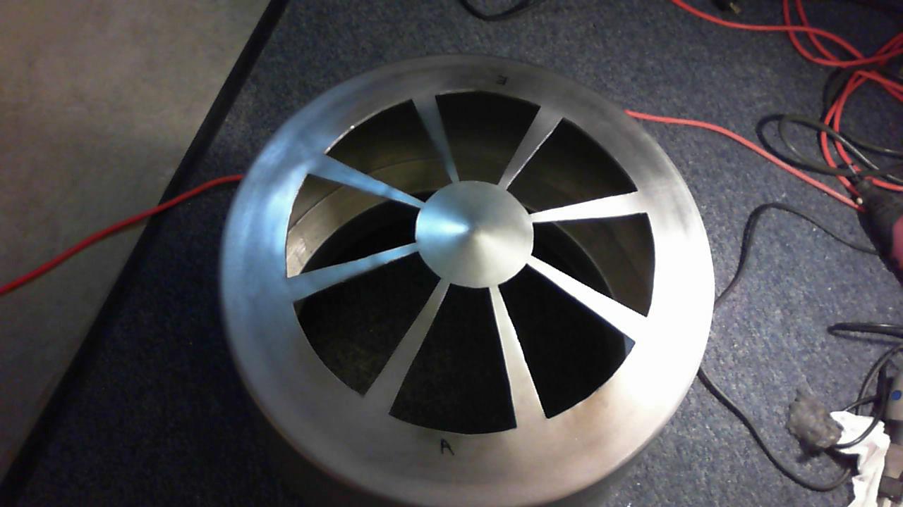
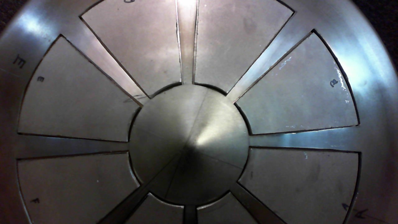
Started working on the R5 head as I started collecting all of the components. Using Drew Harts template, I traced the pie pieces on the dome after I sanded it down. The dome is an old JAG aluminum spun dome that I have had for about 6 years.
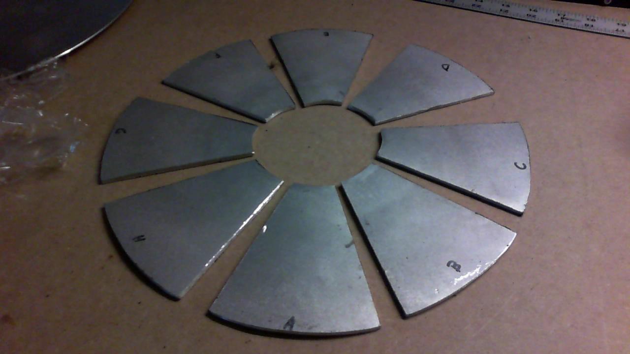
The pie pieces were cut using a dremel rotary carbon fiber wheel to make an initial cut through the aluminum. Then I used a pneumatic metal saw to cut the lines. It was important to try to cut these straight, because the only scrap is the cut aluminum lines. The inner pie pieces will need to go back in the dome.
Once all of the pie pieces were cut out, I sanded them with a belt sander to get the rough edges straight.
On the dome itself, I filed the edges with a hand file to try to get the lines straight.
I have to install the greeblies and cut out the side and back rectangles. I had a heck of a time finding any drawings, but eventually found them. James from COM 8 had them.


As I build the head, I am acquiring other parts of the droid.
January 6, 2016 – Dome Greeblies
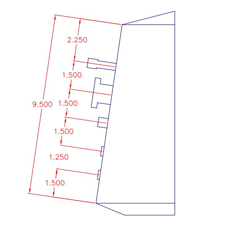
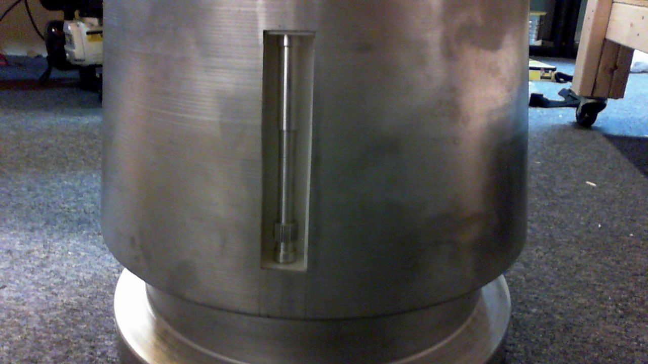
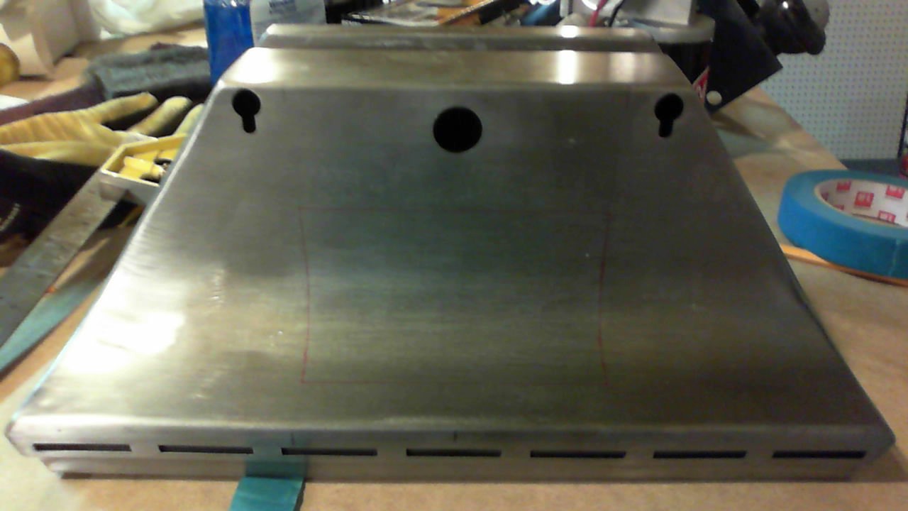
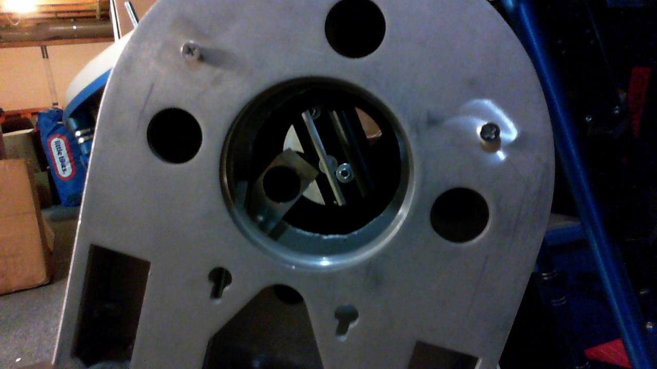
I used the dimensions above to cut holes in the dome and place the greeblies. I used the “poor man’s CNC” method that I used 15 years ago to drill holes in the aluminum. To do this, you create a box in powerpoint using the exact dimensions you would like to place your holes. Print the box, and tape it to your material and punch your pilot holes. It’s much easier than measuring it exactly on the material itself because the printer can create smaller font lines than a pencil.

In the picture below, you can see the greeblie I needed to make holes for. There are 3 holes, spaced 0.375′ apart. The rectangle shape was taped to the proper location, and you can see the pilot punches I made at the corners. Once they are punched, drill using the right drill bit.
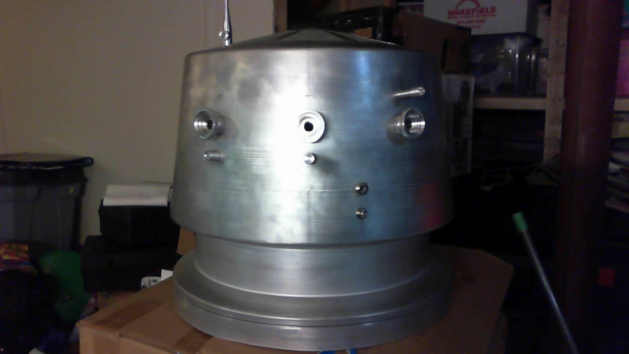
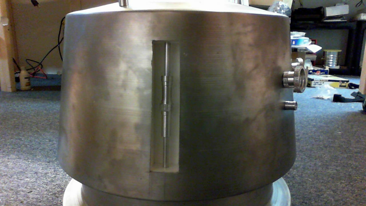
Drilled all the holes and installed the greeblies.

Looking at the pics of this vs. pictures of R5 online, it feel like the eyes are too wide apart. If I redo this, I would need to repunch the holes and bondo the holes I previously drilled. Grrrrrrrr………
2016.01.08
I built the boxes on the head using some spare plastic I found in my basement. They are about 7 inches tall and 1.5 inches deep and wide. They were glued with CA glue for the initial fitting and then reinforced with hot glue on the back. Holes were drilled in the center of the top and bottom plate to attach the greeblies.
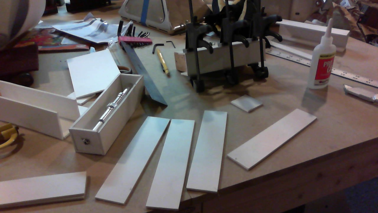
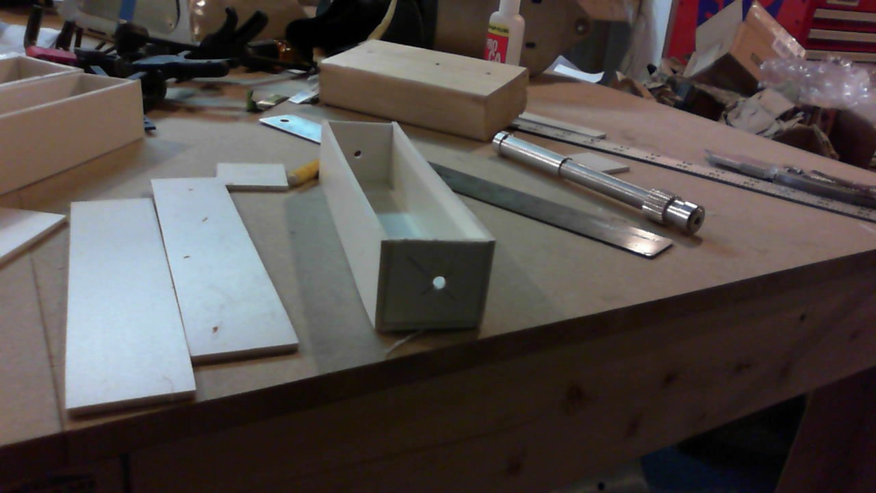
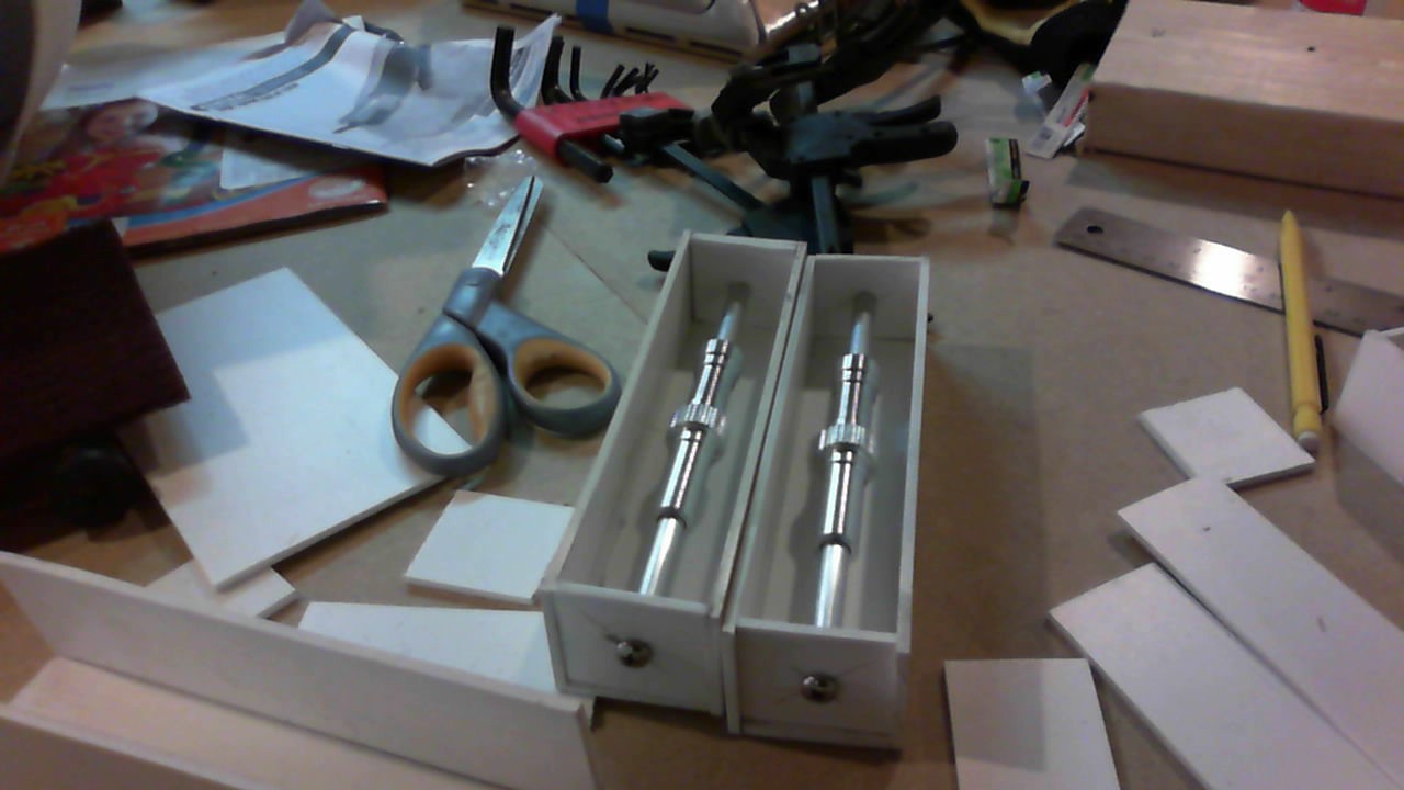
I added another piece of plastic flush to the face so I could attach it to the dome.
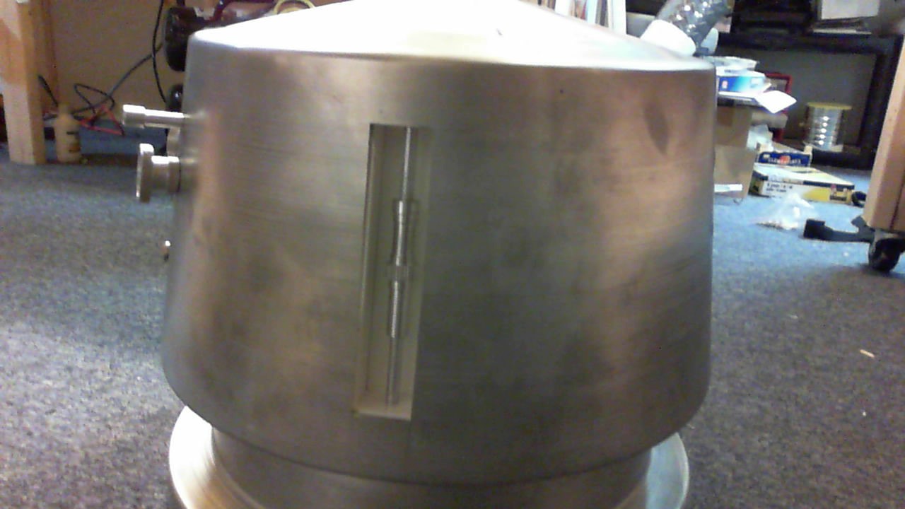
I also temporarily assembled the head with all of the pie pieces and boxes that I just made.

I still need to fix the inner rounded arc of the pie pieces so they look uniform.
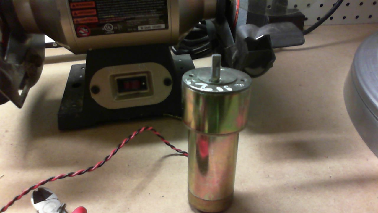
I also started to put together the mechanics of the foot drives. The foot drive frame is an old JAG frame which came with the wheels, pulley belt, and keyed gears. I got the NPC motors from the Robot Marketplace.com. I used to get all my old battlebot motors from there. These are much smaller and were much cheaper! 🙂
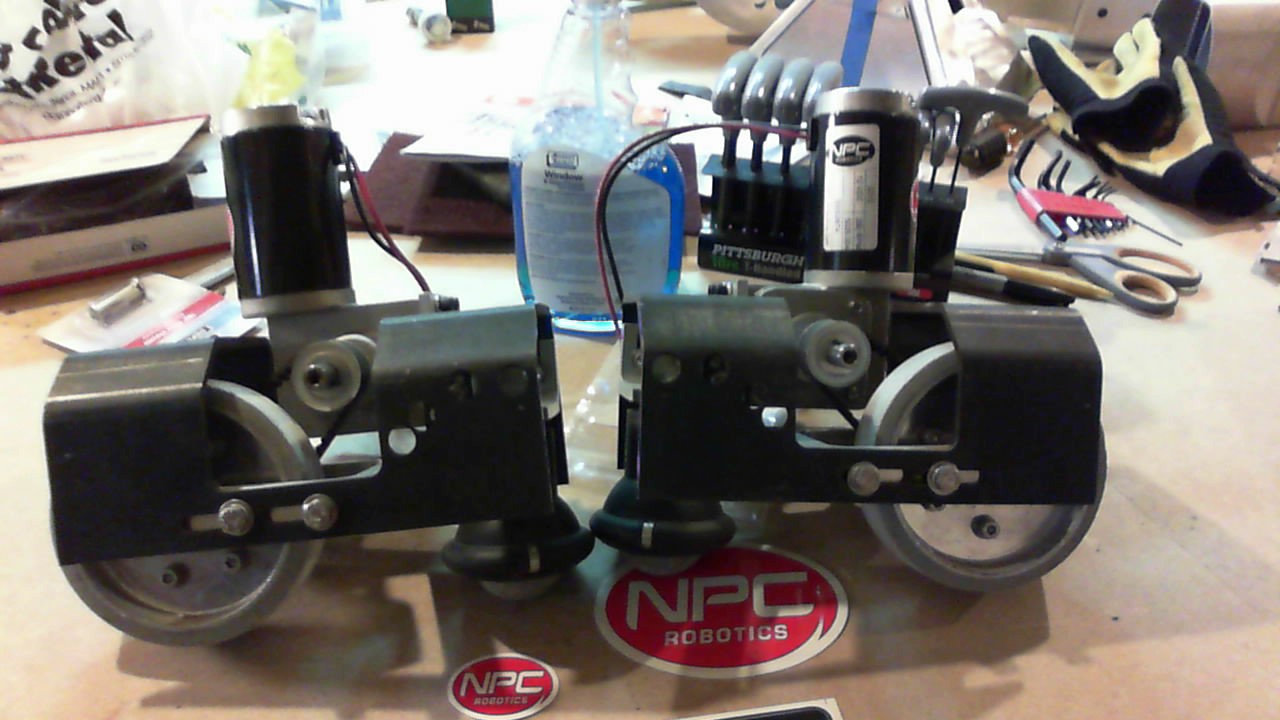
I think I will fix or replace that 360 ball that’s in the front of the drive mechanism. It’s kind of rough rolling. Hopefully a small caster can replace it.
2016.01.10
Worked on the foot shells and the foot drives today. What a Pain!!!!!!
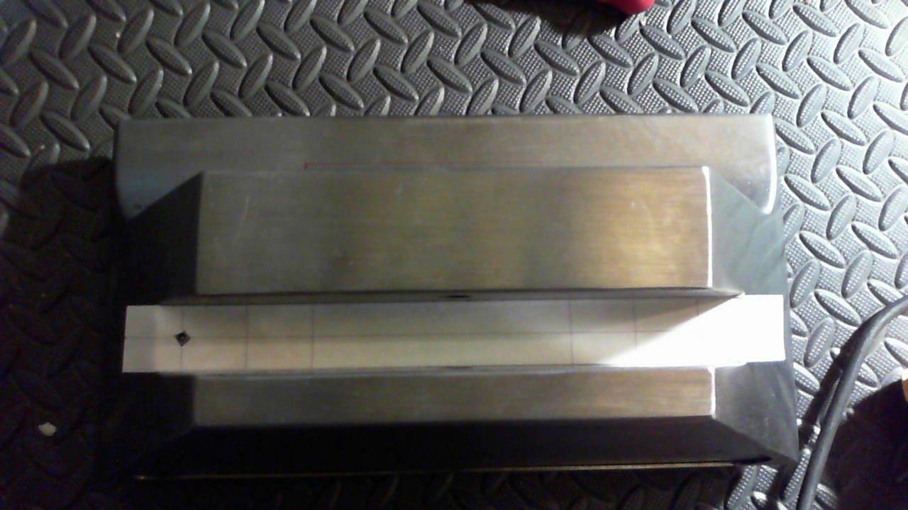
After looking at reference photos and understanding the battery box, I needed to cut out the inside of the foot shell to allow the foot drive to be able to be connected. Side by side comparison made it look like a 5 inch wide by 3 1/8 inch tall box could be cut out of the center. I don’t think there is any magic to this, so I just started cutting.
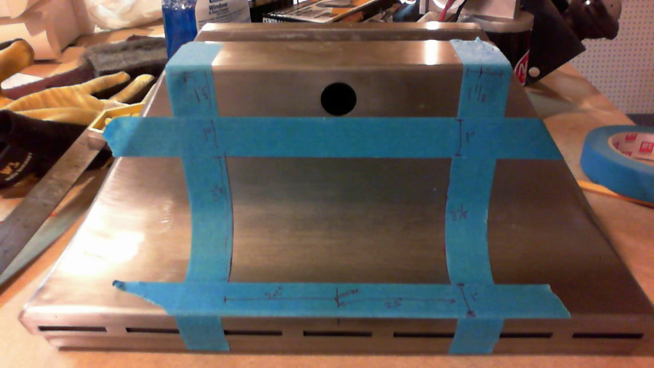
I used a combination of the dremel and the pneumatic metal saw to cut out the box. The tape was just used to create straight lines . I drew a fine sharpie line on the inside of the tape and pulled the tape off. I ended up using one dremel cut off wheel for each side of the rectangle. The pneumatic saw worked too, but it was too slow.

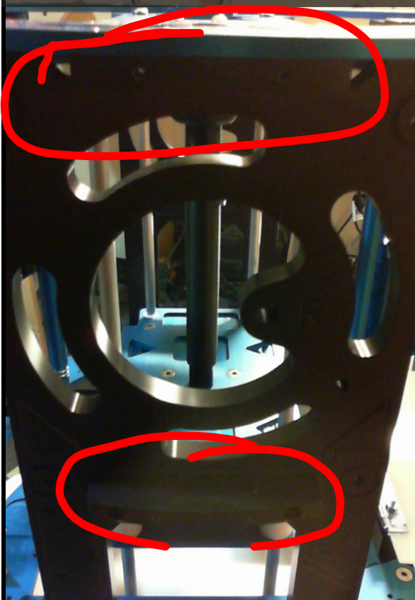
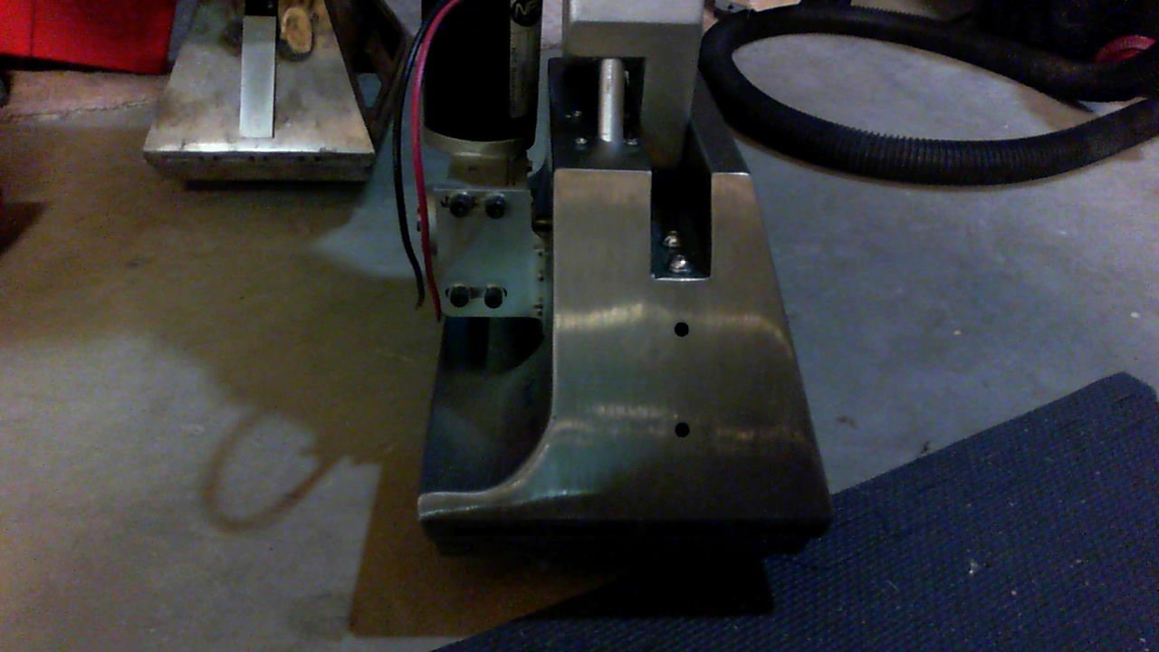
I also had to drill the holes in the top of the foot so that the foot drive could connect. I decided to mount the bracket as far back as possible so that the drive wheel had enough space to be pulled forward to create tension on the belt. This is a little risky since I’ve seen pictures of people that have replaced the omni ball with a caster, and the caster ends up catching on the lip of the foot. But I think it’s better to have the belt tension correct than have it loose. So sizing it up wit the rectangle hole I made, I realized I had to make the hole bigger. The red marking below shows the part that needs to be cut out so the motor mount has enough clearance.
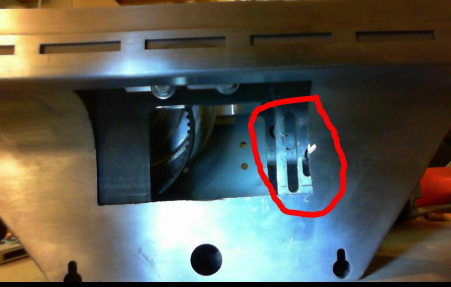
So I cut it again and gave it a wider opening. I didn’t really measure it, I just eyeballed it.
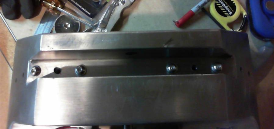
After I cut it out, I dismantled the whole foot drive so I could drill the holes to mount the foot drive to the shell. I got 4 of the 6 holes right and had to widen the other 2. Then I bought screws to cover up the damage. 🙂
In the picture, the right side is the front.
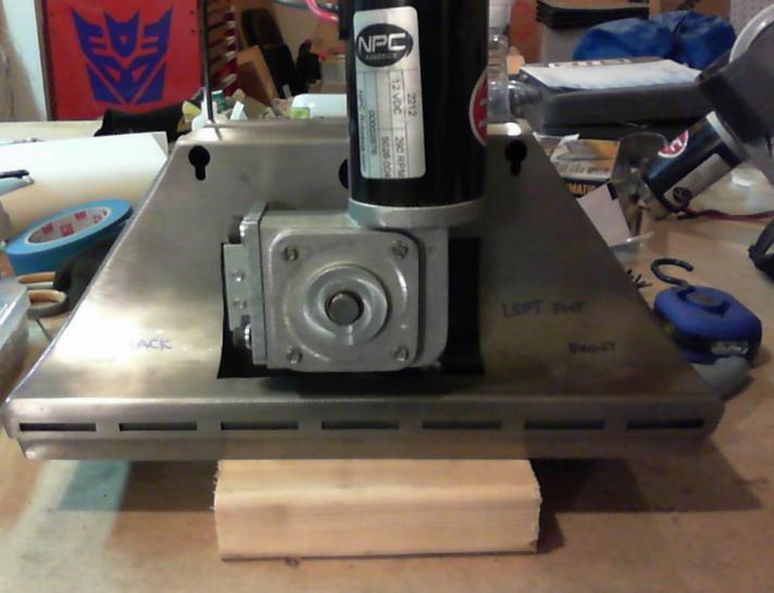
Here’s what the finished foot assembly looks like. It looks simple but it took all day to get one foot done. Alot of fitting, unfitting, cutting, repeat.
To assemble here is the order of assembly, starting with completely dismantled parts:
- Attach the wheel and axle mount to the drive frame using the 4 bolts on the side of the frame.
- Attach the caster and mount to the frame using the 4 hex bolts. Make sure the frame is level.
- Place the frame inside the foot shell, and screw in the bolts on the top channel of the foot shell to connect the frame to the shell.
- Flip the drive upside down, and remove the omni caster. This gives you space to use a hex wrench.
- Insert the motor gear through the hole in the shell, and make sure it’s inside the belt. Loosen the wheel if necessary.
- Align the motor mount on the outside of the shell, through the hole in the shell. Screw in the 4 hex bolts from the inside of the shell to the motor.
- Replace the omni wheel.
- Push the wheel toward the rear of the shell, and tighten the b
2016.01.15 – Commando 8 Frame arrived
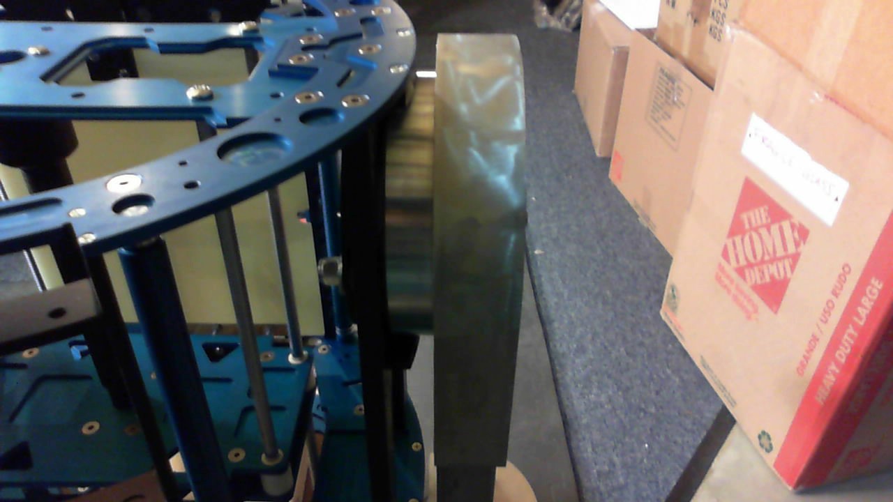
Yeah! Got the Commando 8 A-1 frame today. I’m almost scared to touch it, but I also want to make sure I have all the pieces I bought.
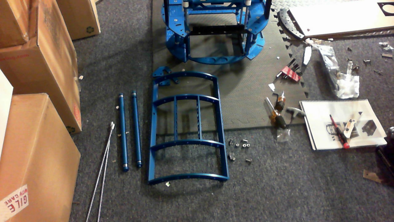
Here’s what it looks like out of the box.
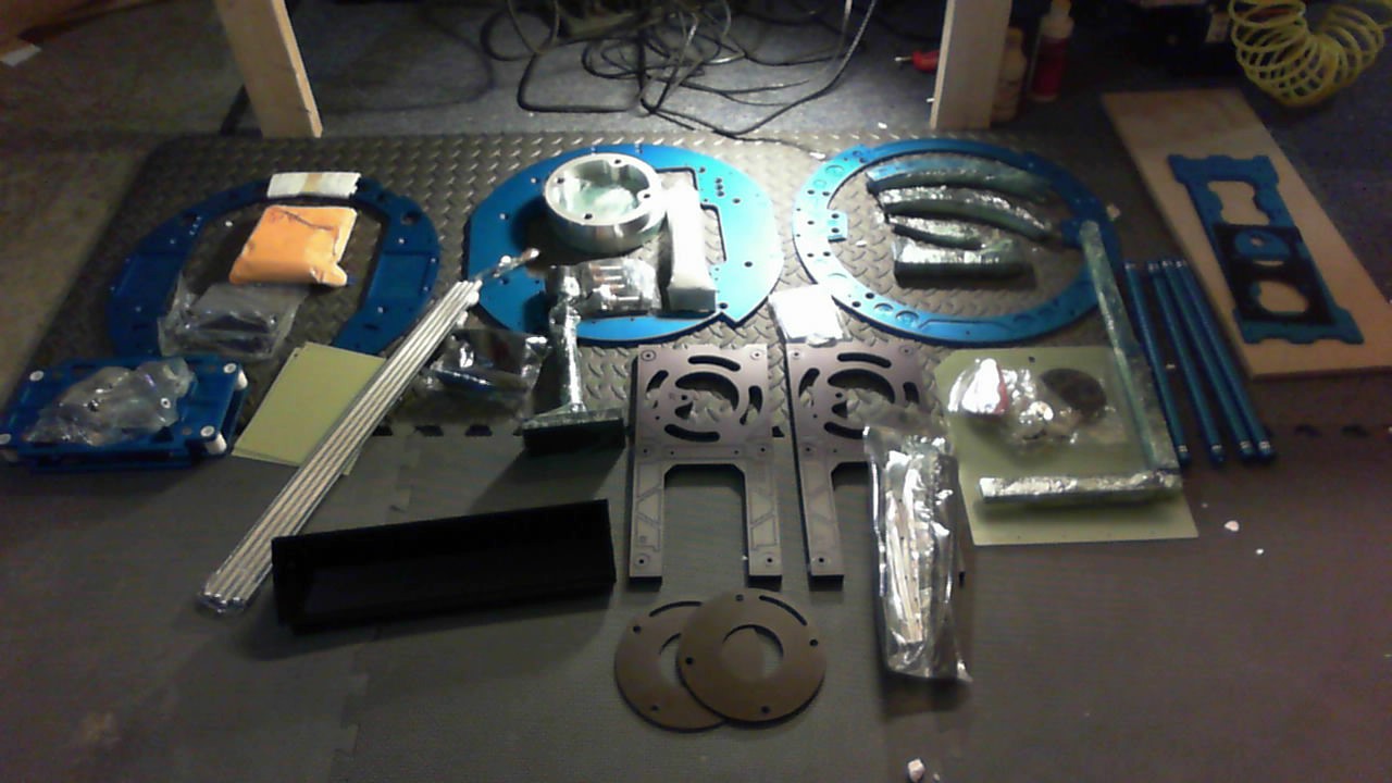
Its like a new Lego set for adult nerds! 🙂
The instructions Commando 8 provides are great! I definitely suggest you get the PDF of the instructions so you can zoom and see all of the detail. This is one thing where you really don’t want to make a mistake.
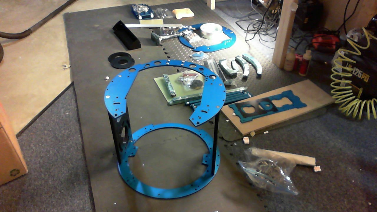
Here are some build pix.
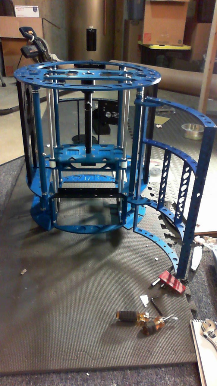
Top and center plate attached to the side plates
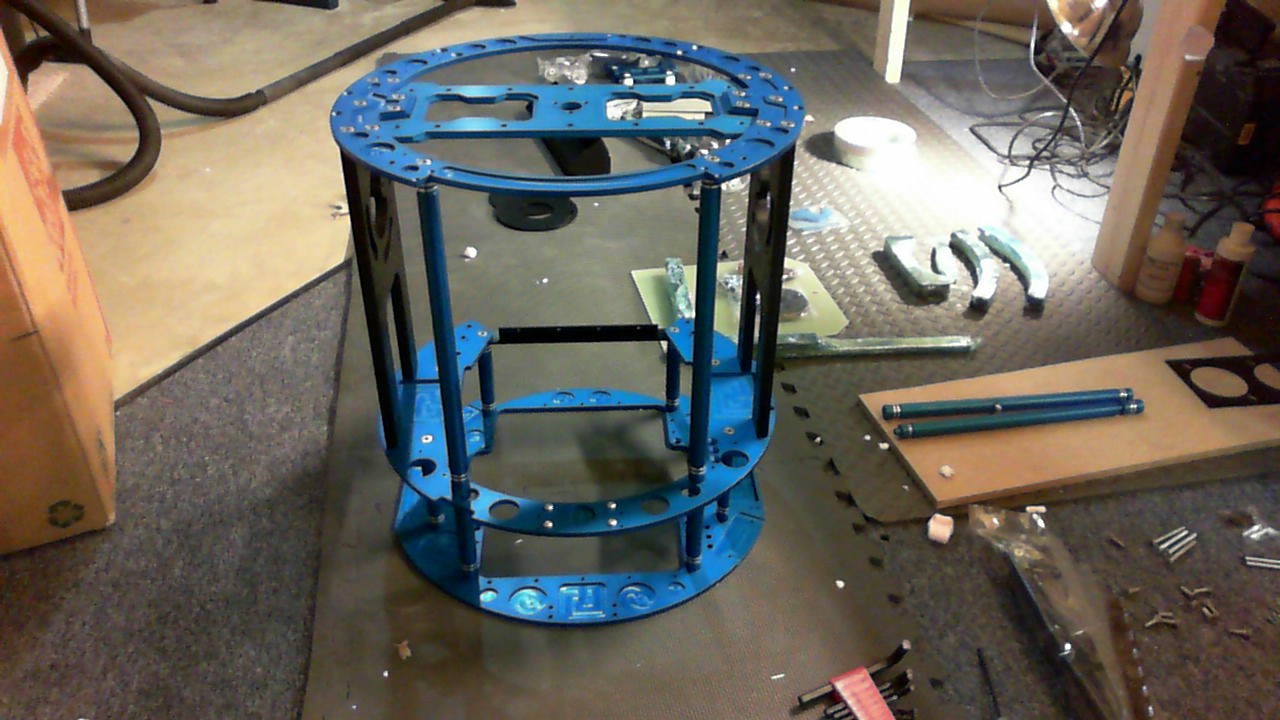
Added the long support bars and center support – hard to see

Short support bars, the bottom plate and the flip down panel bracket
Utility arm carrier and the charger bay.

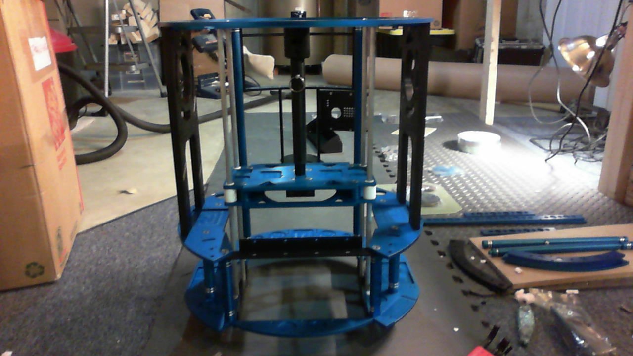
Center foot elevator. This allows the center foot to go up and down and be in a locked position.
Rear door assembly
Attached door hinges, support bars and latch.
From opening the boxes to this point, it took me about 2.5 hours with a few breaks in between. I’m not rushing through it, since I am really taking my time to make sure I don’t strip any of the screw heads or threads. Those 4-40 screw are really simple to strip.
The directions are really simple and are about as basic as assembling furniture from Ikea. The screw holes are all countersunk so its really simple to determine which side needs to face the correct direction. Com 8 also provides plenty of callouts or warnings in his instructions to make sure the assembly goes OK. Very very happy with this kit and so far I would recommend it to anyone.
Tired……
2016.01.16 – Com 8 assembly continued
I finished more of the assembly today. On the list were the following items:
- Flip down electronics board
- Skin blocks
- Battery side plates
- Locking leg assembly
- Pitman arm assembly
Doesn’t sound like much but it took another 2 hours. I also ended up making a “custom” wood table for the droid so it could stand up. This was done to attach the legs and so I’d have a goto stand for the droid for repairs. I tried various crates, containers, buckets, etc. and had to shim with 2×4 pieces for the legs to be in the right position. I finally just put a few scrap pieces of wood together to fit the bot.
Here are some of the build pics.
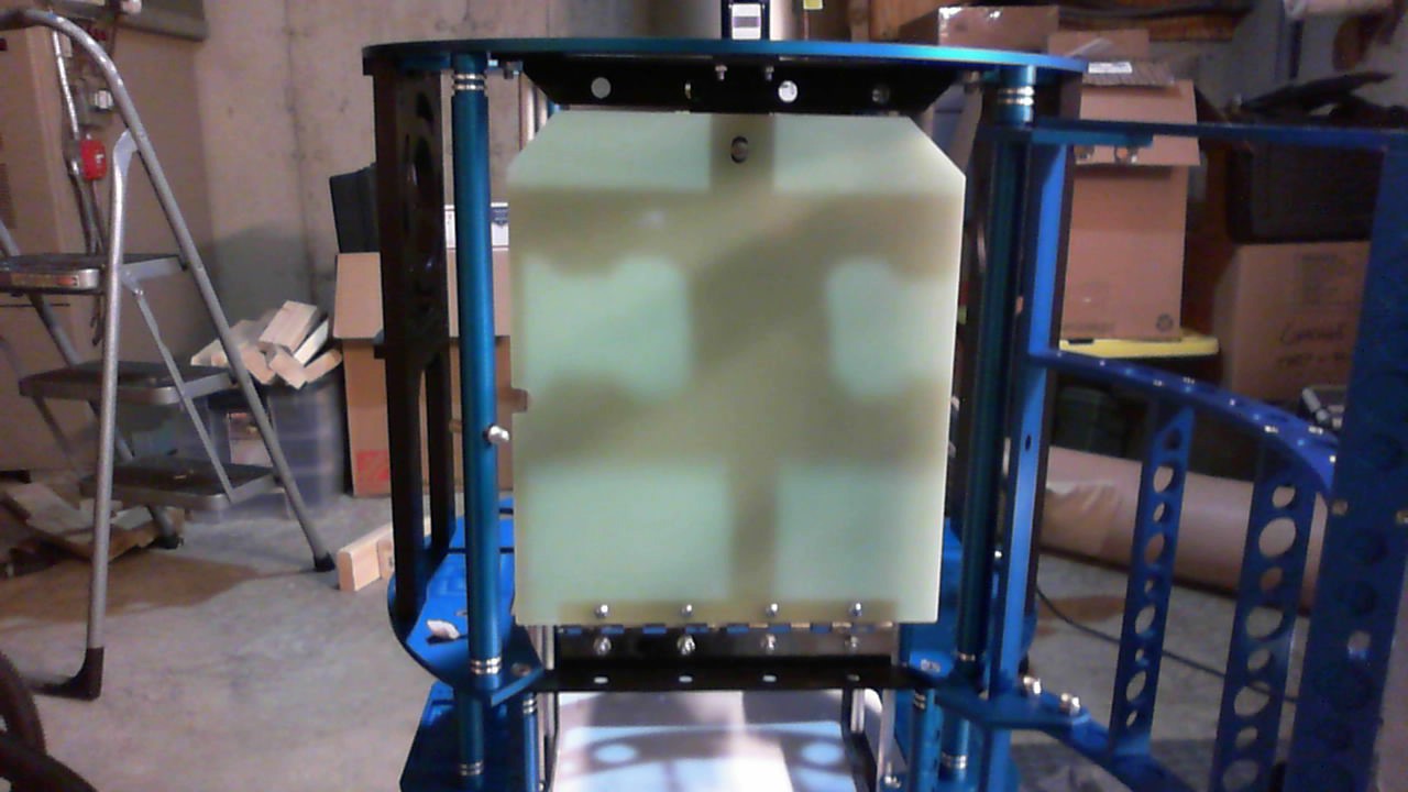
Flip down electronics panel in the up position. It’s held by a spring loaded locking mechanism at the top, similar to a cabinet. Push to lock-in, push again to unlock.
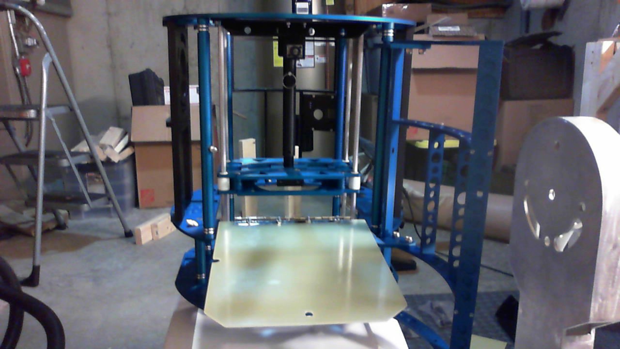
Flip down panel in the down position.
Skin blocks (3 on each side panel). Kind of hard to see since they are black on black.
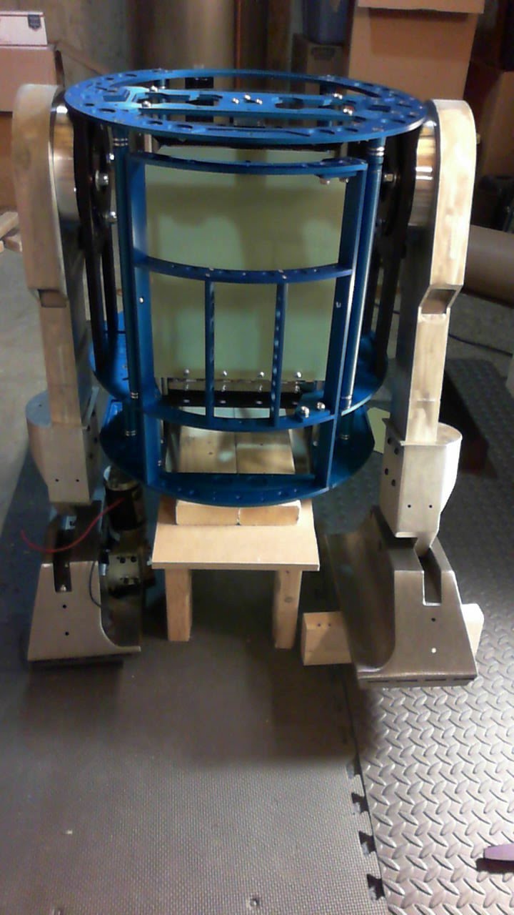
Leg installation. This was simpler than I thought. Really it’s just a sequence of washers and bearing held together by a locking plate and locknuts.
You can see the custom stand I made for it too. The droid is really starting to look like a droid now. 🙂
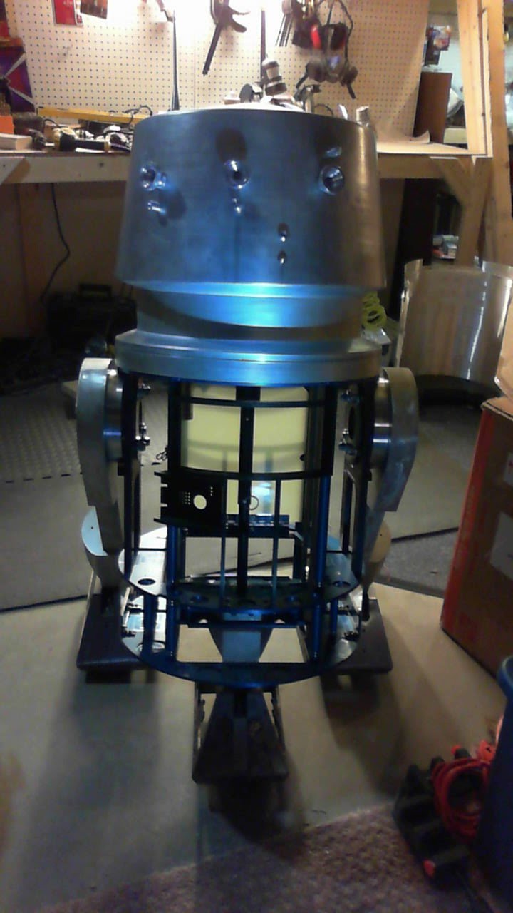
Test fit with the dome. 🙂 Holla! Hallow!

Flatted edge of the pittman drive shaft.
Battery side plates. The battery spots on the frame are really small. I’ve got to do some research on how others mounted bigger batteries. This frame is build around four 12V 5A AGM batteries. That’s only 20A total if I stick with 12V. Not sure that’s what I want to do.
Calling it quits for today. But it was a good day!
2016.01.24 – The other foot
Worked on the other foot today. Not too bad, just alot of cutting. This time I got the EZlock Dremel and the metal cutoff wheel. Only went through 2 of them. I also used a template to make the holes in the top channel using a powerpoint file. I created the template and cut the first hole where I thought it should be placed. Then I placed the template on top to get the rest of the holes in alignment. The big square hole on the side of the foot was eyeballed and cut. Seemed OK.


Next – I need to work on the center casters and try to roll him around. I’m debating whether or not to use my Vantec from my old battlebot. Definitely overpowered, but that thing is just sitting in an old bot which hasn’t moved in about 15 years. Also working on the electronics setup.
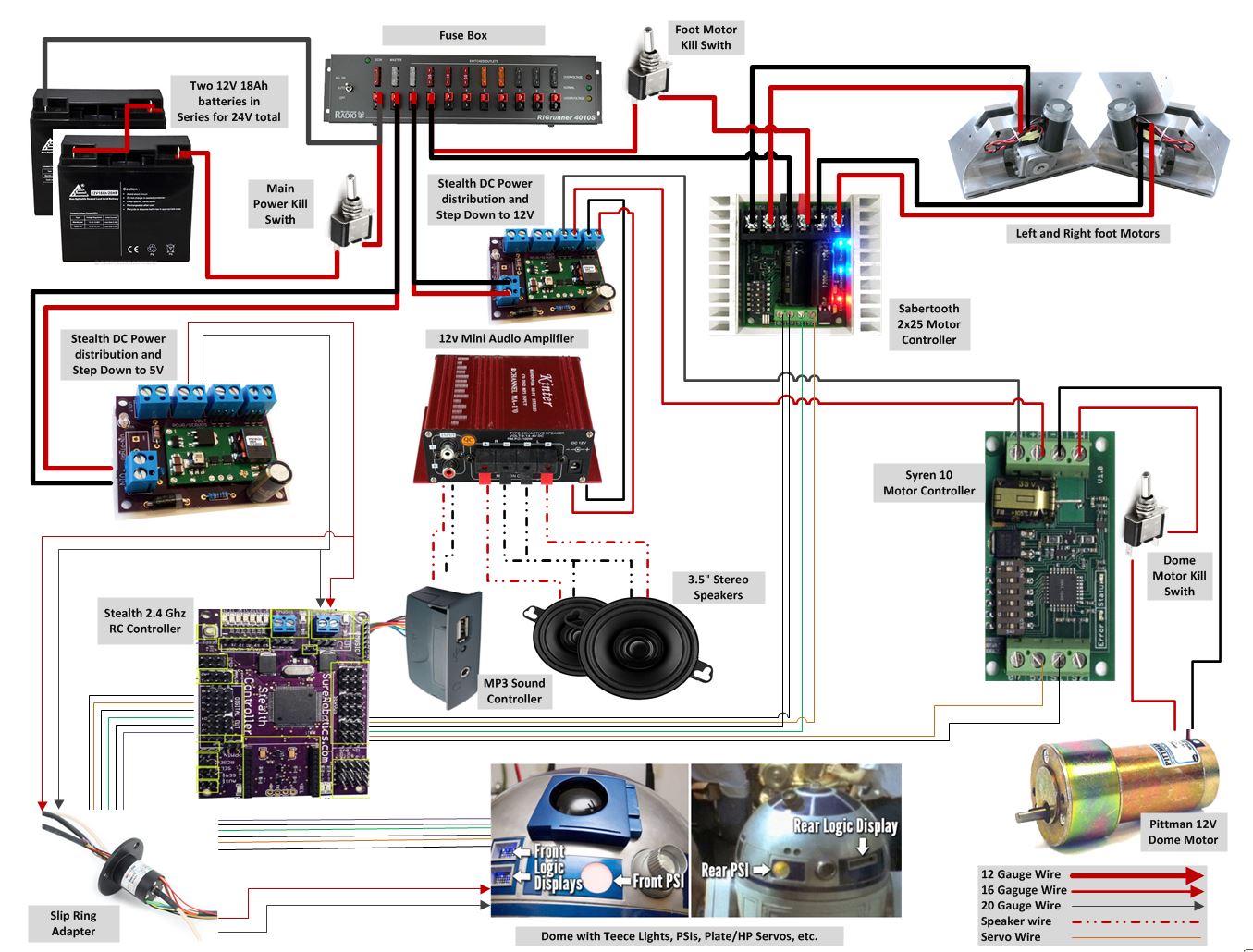
Found this which may help.
http://astromech.net/forums/showthread.php?22325-Wiring-Diagram-with-Stealth-NPC-RSeries-Sabertooth-Syren

Here’s another link on electronics:
http://astromech.net/forums/showthread.php?22280-My-Basic-Wiring-Diagram/page2
These are potential casters that I may use.
http://artoo48.rssing.com/browser.php?indx=13855916&item=4

Manufacturer: Proctor Glove
Part Number: 3RS
Description: 3″ Rubber Swivel 125lb
UPC: 7 80272 000003 7
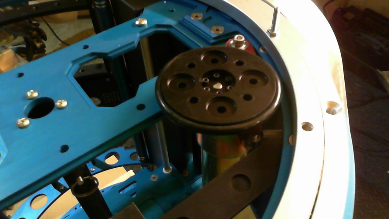
2016.01.26: Rockler bearing and pittman mount
Not a huge update, but I was able to drill the 1/4 holes through the rockler bearing and countersink the holes using the 82 degree countersink bit. Added the 10-24 1.5 inch screws to the other side and screwed the hole thing down with 1/4-20 3/4 inch tapered screws. Directions say to use 7/8 inch screws but they haven’t arrived yet.
I finally got an allen wrench small enough (0.005) to fit in the set screws for the pittman wheel mount. Set those, and installed it on the frame. I tried to test it, and realized the motor required a 24 volt power source. I only had an 18V on my drill and it was able to spin around. It’s not completely mounted since I need a 1/4-20 1.5 inch screw to hold in the tension spring.

2016.02.04 – Front foot assembly
Got some wood during work sometime this week and started to cut out the assembly to hold the casters on the front foot. It’s basically just a few different sized trapazoids made out of wood and glued/screwed together. Who’d of thunk this block of wood would have taken 4 hours to build and install.

This isn’t the final shape. I had to cut out notches on the top to allow the ankle screws to go in. Then I cut holes on the top for screws that connect the wood block to the steel foot. There is a hole going through the middle of the block to allow me to screw a nut in there. Not sure it’s going to come out. I’ll get pics of the final tomorrow.
2016.02.08: Ankle locks! So annoying
So the COM8 frame has in-leg ankle locks, and these are such a pain to install. I had to cut a 3 inch hole inside of the leg, cut holes in the foot shells and ankles themsleves and install the ankle locks. It took over 9 hours to do this, partially because to test and install, it takes about 20 minutes to assemble. Once you assemble and notice parts hanging up, you need to disassemble and cut.
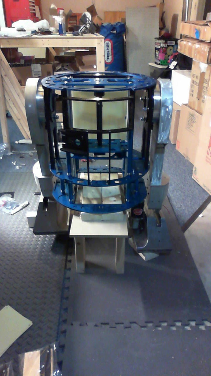
I was so annoyed doing this, that I didn’t take too many if any pics at all. Here’s what the end product looks like, and I still haven’t figured out the whole locking part out yet. He doesn’t tip forward, but he does tip over backward when in 2 leg mode.


I ended up putting a 1/4 shim in the center foot front caster because it wasn’t hitting the ground. These ankles & foot combination are known for not being setup right so that the foot doesn’t hit the ground at the right angle. In 3 leg mode, it’s not too obvious, and will take too much work at this point to fix it. I think I may just end up getting a new front foot if I’m not happy.
2016.02.09: Wooden mount for the R5 dome
I don’t even know what this thing is called, so I’m calling it the wooden ring mount. It’s basically the interface between the rockler bearing and the dome, connecting the two so that when the rockler bearing turns, the dome turns. I saw my friends Bob and Kevin make one once, so I thought I’d make the same thing. The old JAG R5 dome that I got doesn’t have the connector ring, so I had to make one. The R2 dome I have, has one included. But since I’m making the R5 dome first, I thought I’d give it a shot.
I needed dimensions for the ring, so I took the rockler bearing drawings and took the inner diameter from it. I also took the locations of the bolts that come out of it so I could cut out the slots that allow the dome to rest on the bolts. For the outer diameter, I took the dimensions of a dome and subtracted the thickness of it to get the inner diameter of the dome. I used that to make the outer diameter of the ring. That wasn’t such a good idea since I had to do alot of sanding to get it to fit into the R5 dome.
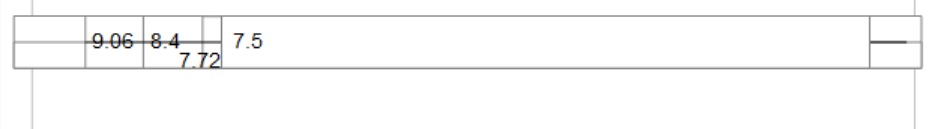
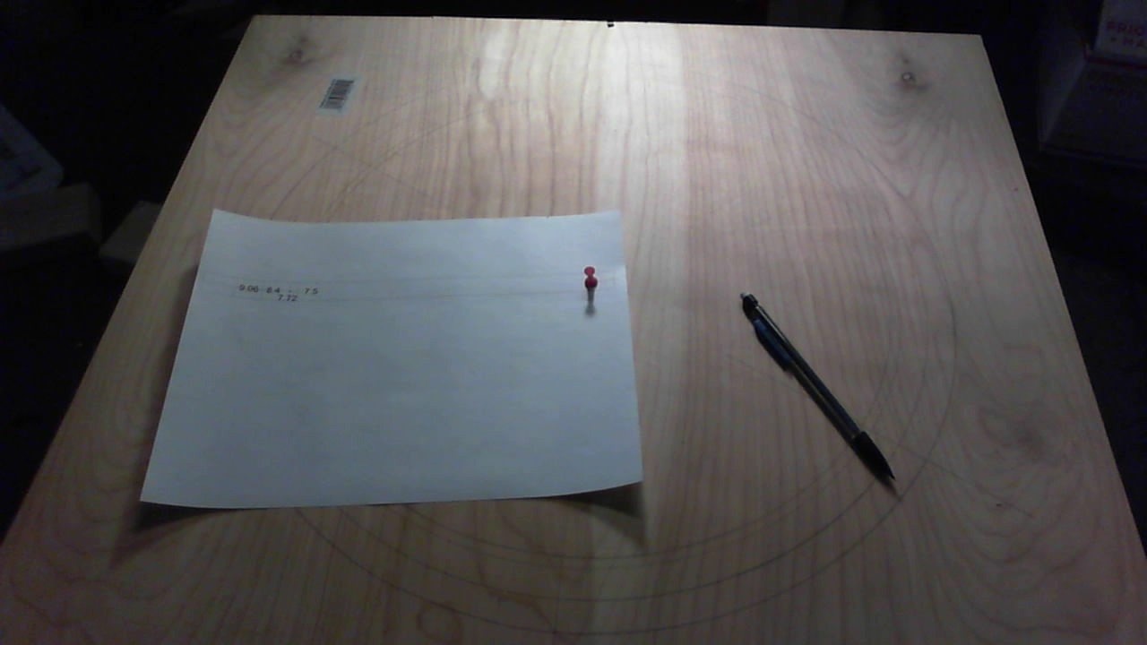
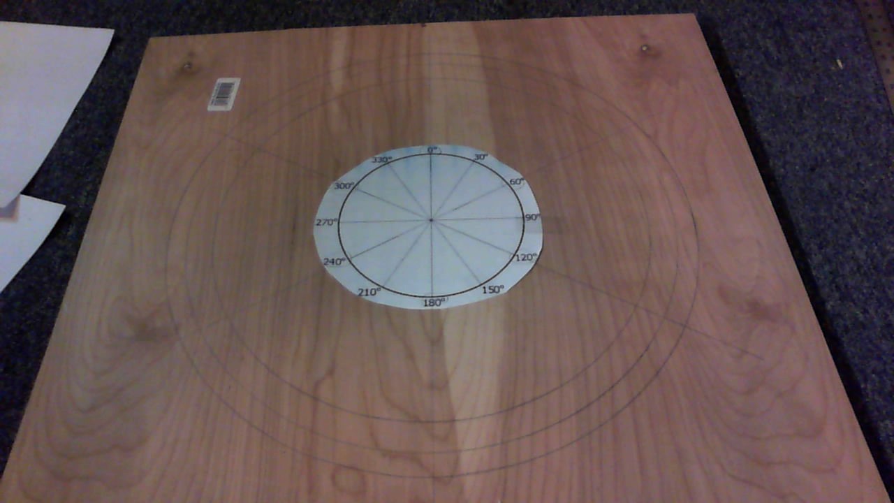
So here are some shots. This is my make-shift compass. Since I knew I couldn’t measure the diameters accurately using a ruler, I drew boxes in Powerpoint at the precise dimension I needed. The powerpoint looked something like this. The 7.5 was the inner radius, the 7.72 was the bolt location and the 9.06 was the outer radius. I took a thumbtack and put a hole in the right intersection and a small hole on the left “cross-hair”. I stuck the thumbtack on the right intersection and stuck a pencil in the location where I wanted to draw a circle. The picture below shows how I did this.
Then I had to draw the 60 degree lines to pinpoint where the bolt slots would go. I used this template and taped it to the center of the circle. Then I took a straight edge and extended the lines to create the exact location of the bolt holes.
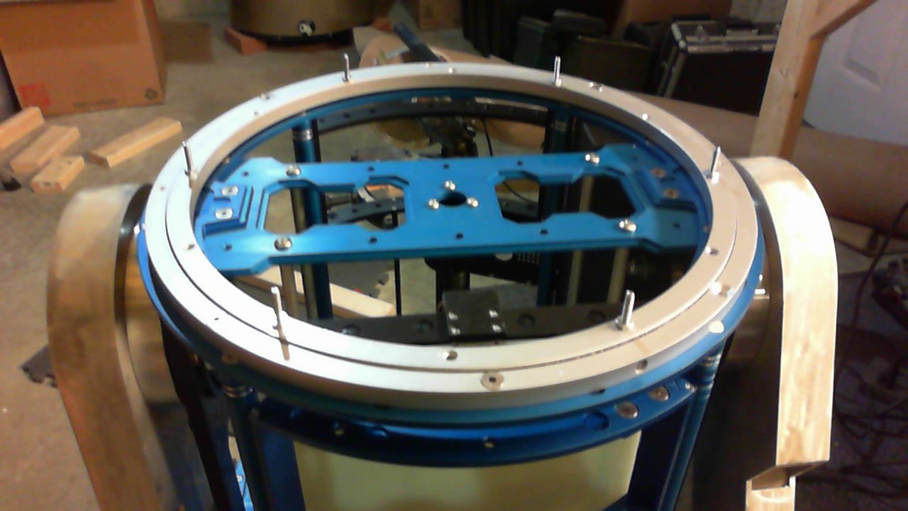
Then, I took a jigsaw and cut the outer and inner edges to create the ring. Then I drilled the holes for the bolts. Here is a test mount.
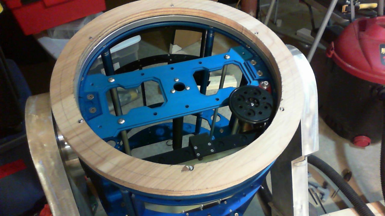
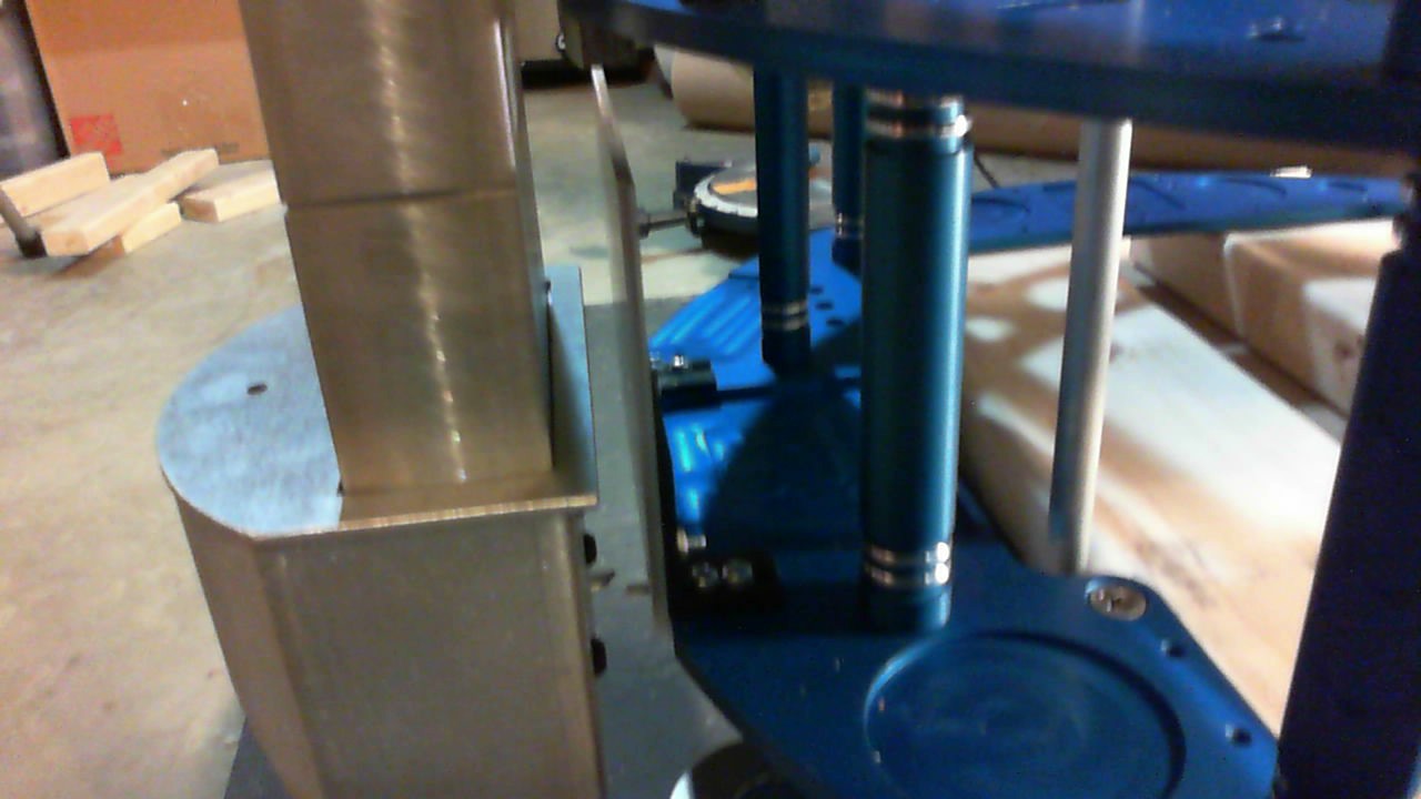
You can see the outer diameter is much too large, so I sanded the outer edge ALOT of times using a belt sander to get it to fit into the dome.

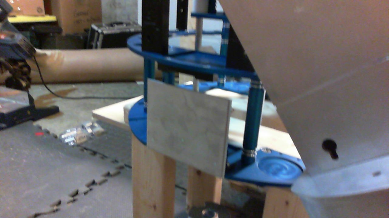
You can see it’s a good fit. I haven’t glued it in yet as i need to see where it’s supposed to sit relative to the skins. Right now, the fit is sufficient to move forward.
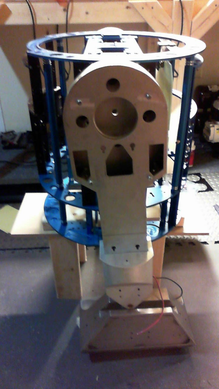
Here’s what it looks like on the body.
Onto the electronics to get this guy moving.
2016.02.13: Motors and Speed Controllers Test
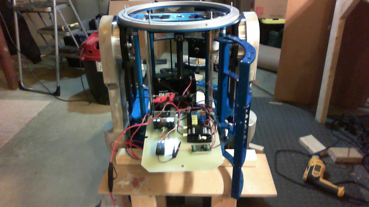
Finally at the point where I can test the chassis, motors and speed controllers. Everything is basically connected using temporary connections, while I wait for the Anderson Powerpole crimper to come in. Battery is connected to a cut-off switch, connected to a distribution box with 5-20A fuses, connected to the speed controller (Sabertooth 2×60) which is connected to the RC receiver (aileron and elevator channel 2&3 on the Frsky L9R) and motors (separated by switches on the positive lead).
The dome motor is a 24V, so from the distribution box (12V), I put another smaller battery in series creating the 24V loop. The Styren10 speed controller is connected to the 24V, the receiver (rudder connection) and the Pittman motor.
Not sure if this will be the final layout, so everything is only taped in with double sided tape.

Here is a video of my first steps.
And with the dome on.
The rest of the build
So from March 2016 to June 2016 I finished the build. I didn’t do too many log entries, but I did take some pictures. You’ll see them below. The rest of the build was to get the skins on, fit the greeblies with goop, epoxy or hot glue, and finish off some of the electronics. After painting all of the skins and head, I also made a “bad motivator” based off the e cigarette set used here:
http://r5-d4astromechdroid.blogspot.com/
I used a cloud beast atomizer, connected with a relay directly to a 4S lipo. The actuator is slow, but it can push 150 lbs linearly. I previously tried a car door actuator, but it kept breaking due to the high load. So I bought a real actuator for robotic builds. Like I said, it’s slow, but reliable.
There is also an FPV (first person view) camera where the charger typically goes. So I could theoretically drive him around without looking at him at a con – but leaving a 200 lb robot alone with kids, controlled by a $35 camera is probably not a good idea.
Here’s how the FPV works:
Here are the pics of the rest of the build.


Finished R5D4
Here are some final pics of the R5D4. I also built a “charging bay” for it out of wood and some cheap Amazon LED rope. The jawas are were used for Rhode Island Comic Con 2016.


